
View Our Range


Pumps account for 10% of the world’s electricity consumption and in the average industrial plant, pumps consume up to 50% of all the energy usage on site.
But up to 90% of these installations are inefficient. If every pump system were installed to its best efficiency, the energy savings would be the equivalent to powering 1 BILLION HOMES.
Considering there are nearly 8 billion people on this planet, making efficiency changes to pumping systems alone, we could cover an eighth of the worlds annual energy consumption!
.jpg?width=257&height=193&name=RB%20ultrafiltration%20(3).jpg)
Europump, the European council for pump manufacturers, claim that European legislation is currently only looking at the requirement to optimise the design of energy-intensive products, including pumps. Europump’s study found that if just the region’s water pumps were looked at in isolation, with a view to reducing their electrical consumption through better PRODUCT design, savings of 5 Terawatt hours could be achieved. But if a ‘WHOLE SYSTEM’ approach is taken, that is looking beyond just the pump but also the application and system in which the pump operates, then savings of up to THIRTY-FIVE TERRA WATT hours could be achieved. That is A SIX HUNDRED PERCENT increase in energy savings, simply by looking at the bigger picture.
As a quick reminder, 1 terawatt is 1,000 gigawatts, or a billion kilowatts, or a Trillion watts! A THIRTY-FIVE TERAWATT hour saving is the equivalent annual energy output of FOUR large coal fired power plants. Or to put it another way, because I am British and enjoy a cup of tea - 35 terawatts is enough energy to boil the kettle and make 800 BILLION cups of tea! In 2016, the world's electricity consumption amounted to approximately 218 terawatt hours, so process improvement and energy savings just on European water pumps could offset 6 weeks’ worth of global energy consumption every year!
It is clear we can view this as a win / win opportunity because increased efficiency savings means reduced costs and increased profitability for the business, whilst also reducing the carbon footprint for the planet. Crest Pumps have specialised in the manufacture and supply of chemical resistant pumps for over 45 years and in this time we have seen all kinds of systems that due to their inefficient design or installation, result in costing their user huge amounts of money over time. These design inefficiencies are a great passion of ours because they represent a huge opportunity to find these efficiency savings and reduce our carbon footprint.
But these huge numbers of billions and trillions can all sound rather daunting, so we are going to being with the much smaller number, 6. This paper is going to share with you 6 critical elements that are relatively simple to follow but have the potential to increase your plant efficiency and energy savings by up to 600%. But before that, we need to recognize all the elements that contribute to the whole life costs of a pump.
Life Cycle Cost (LCC) Analysis
LCC analysis is a management tool that can help companies minimize waste and maximize energy efficiency for many applications, not just pumping systems. By understanding the life cycle costs of a pump, we break down all the individual elements of a pumps cost over its life and can see how making simple changes, can lead to a far greater improvement in plant efficiency, reduced running costs and a reduced carbon footprint.
When specifying a pump and making decisions when under constrained budgets, it is tempting to think short-term. High importance is often given to up-front procurement costs, with less attention to the long-term future costs. But this is where a life cycle cost analysis approach should instead be used. This considers every area of cost when it comes to the operation of a pump over its life. Remembering that pumps can account for up to FIFTY PERCENT of all the energy consumed at an industrial plant, the initial procurement and installation costs are only 17% of the overall lifetime costs.

(graph / diagram of comparison of cheaper, less efficient pump)
The Life Cycle Cost Equation shows every element that contributes to the overall economic and climate cost over a pump’s life and so it is vital that every single aspect is scrutinised. But in this paper, we are going to focus on just two of these eight sections to help bring the biggest improvements in overall cost reduction.
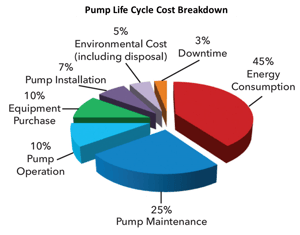
Normally, the biggest surprise when seeing a pump Life Cycle Cost broken down like this, is that the initial purchase price of the pump is a MERE 10% of the overall lifetime cost. As mentioned earlier, when project budgets are squeezed at the design stage, it is a very short-sighted view that can considerably impact the overall running costs. For example, the smaller the pipe and fitting diameters, the lower the cost of acquisition and installation. But on the flip side, smaller diameter pipes will require more power consumed by the pump to achieve the same duty. Therefore, the short-term capital saving of the pipework will soon be eclipsed by the higher ongoing energy consumption costs of the pump.
Through life cycle cost analysis, we can identify that potentially investing more on the initial cost of the most suitable pump and system design, this initial increase in purchase cost will be dwarfed by the savings in energy consumption over the life of the pump system.
Now I understand that your sceptical alarm bell is now ringing! “I’m reading a white paper written by a pump company advising me to spend more money on pumps!” But that is not the motivation for this paper, We only recommend you look at the numbers - calculate the long terms savings through life cycle costing, so that you have all the knowledge and data to make an informed decision about the best long term practices for your company.
Figure 2 identifies the biggest factors of a pumps life cycle cost are maintenance accounting for 25% and up to FORTY FIVE PERCENT of the whole life cost is accounted for by its energy consumption.
From our 45+ years of experience in the pump industry, this paper will now share with you the 6 biggest and most common opportunities that will help you to reduce energy and maintenance costs, leading to you enjoying increased plant efficiency, productivity and profitability. And ultimately help reduce all our impact on the climate.
To carry out your Life Cycle Cost comparison, you can do so here and enter the data into our quick and easy to use LCC Calculator.
Tip 1 – Operating at The Best Efficiency Point
In order to maximise efficiency and minimise energy consumption costs, the first crucial point is making sure the pump is operating at its best efficiency point. A pump performance curve is developed for every pump and plots the performance of the pump showing total discharge head and flow rate. For a centrifugal pump as the flowrate increases, the discharge head reduces and somewhere along this curve will be the pumps best efficiency point.
At this point, flow enters and leaves the pump with a minimum amount of flow separation, turbulence, or other losses. These are the precise conditions, whereby the pump operates with greatest efficiency and at which it can be expected to have maximum working life and require the lowest amount of maintenance. 
But this curve only describes how a pump performs in isolation from the rest of the plant equipment. How it operates in practice is determined by the resistance of the system in which it is installed. This takes into account restrictions such as pipework and downstream frictional losses from other components in the system. The overall resistance of the system is shown through a system curve, and this shows how the head pressure increases as more flow is forced through the pipework.
By plotting the pump and system curves on the same graph, we find the operating point. This will identify what flowrate and discharge pressure the pump will provide. If the lines do not cross, then this pump and impeller diameter is not suitable for your application. To minimise the pump’s energy consumption, this operating point needs to be as close as possible to the pump’s best efficiency point. Clearly, this data point on the system curve wants to be as accurate as possible. It is quite common that by adding too many safety margins to your calculations it can potentially lead to an incorrectly sized pump being specified as you will be operating much further away from the pump’s best efficiency point.
Figure 3 shows the Best Efficiency Point (BEP) located at the apex of the pump efficiency curve in red and it is at this point, where you want your system curve to intersect with the pump curve. Because it is very difficult to design a system curve to perfectly match the best efficiency point, the Hydraulic Institute allow a larger band of flowrates, called the Preferred Operating Region. Operating within this is larger range of flowrates means the hydraulic efficiency of the pump is still good enough to ensure high reliability and long service life. An even wider range, within which the pump service life is still acceptable, and is set by the manufacturer, is called the Allowable operating region. The limits to the Allowable Operating Region are determined by requirements other than energy consumption, and considers other issues such as hydraulic loads, liquid temperature, noise, power, and Nett Positive Suction Head.
Going beyond this range, there are a multitude of negative consequences that can arise when a pump is operated significantly above or below its BEP that can result in accelerated pump wear and premature failures. To the left of this region, a pump’s flowrate is lower than its design specification and the fluid may not flow correctly through the system, which creates a danger of recirculation. When operating at these excessively low flow rates, it could cause higher loading on the impeller causing excessive vibration and premature seal failures.
Also, with a low flow, there can be problems with heat build-up. Heat is produced by the motor and friction in the pump and this heat normally dissipates through the pumped fluid. But under low flow conditions this may not occur efficiently enough to prevent overheating. The impeller, casing and bearings of a centrifugal pump are precisely engineered with minimum clearances to maximise efficiency. So at higher temperatures the gaps between these rapidly moving components is reduced even further, and if they come into contact it will result in much faster wear and potential damage.
At the right-hand side of the BEP, a pump’s flowrate is higher than its design specification, meaning the pump’s nett positive suction head requirement may not be met leading to cavitation. Cavitation has its own topic shortly, but essentially a flowrate beyond the Allowable Operating Region can result in excess vibration and noise from the pump, placing greater strain on its components and downstream pipework. This will lead to greater maintenance costs and downtime from pump failures.
Tip 2 – Effective Pipework Design
We can see how good Pumping System design and by closely matching the system curve to the pump’s best efficiency point is key to minimizing the Life Cycle Cost. Proper system design not only reduces the LCC, it also maximizes efficiency. For example, pipe diameter must be calculated according to the flow and pressure generated by the pump, but it must also be properly sized because operational costs are directly dependent on piping diameters. Therefore, any efficiency improvements in the pump system come to nothing if the piping and controls fail to support the pump. Potentially, the pipe system could cause the pump to operate so far away from its Best Efficiency Point that it can easily be damaged by operating at the extremes of its curve.
 Therefore, when designing new pipework around a pump system, the piping diameter should be selected based on the economy of the whole installation so that the total cost for pumps and the piping system is at a minimum. Again, when under budget restrictions It can be tempting to reduce the pipe diameter for short term cost savings with procurement and installation costs, BUT, your pump costs will rise significantly as a result of increased flow losses with a subsequent requirement for higher head pumps and larger motors. With these larger components, the costs for electrical supply systems will also increase. But the biggest contributing factor to life cycle costs – that is the energy consumption costs, will increase significantly as a result of the increased friction losses.
So now we know that reducing pipework sizes will artificially reduce installation costs, we can instead provide some more guidance that will help aid more efficient and cost-effective pumping systems.
- On the suction side, make sure to keep the pipe diameter to at least the pump suction size, but preferably a size larger to maintain a suction velocity of a maximum 1 to 1.5metres a second. Also keep your suction pipework as short as possible, with a maximum length of 10 times the pipe diameter after any valves or change of pipe direction. Turbulence can be caused by tight bends, so use long radius bends and full-bore valves where possible.
- Use eccentric reducers, as opposed to concentric reducers, keeping the level side at the top to prevent air being trapped within the pipework.
- Avoid high points in the suction pipework if you can, but at the very least include a vent at the highest point. Air getting into a pump can shut down the pump immediately and sometimes destroy the pump.
- Because we have seen this issue many times in the past, make sure you include pressure gauges on the discharge pipework or at least the ability to check where the pump is performing on its performance curve. Trying to trace a problem could easily be resolved when we have a better understanding as to how the pump is currently performing (or rather underperforming), because as we have seen, the position on the performance curve can help identify exactly what the problem is, depending on whether it is to the left or right hand side of the best efficiency point.
- Size the discharge pipework to minimise friction loss. The lower the friction loss, then a pump with a smaller impeller can be utilised with significant power savings over the course of its lifetime.
Tip 3 – Operating with a Variable Speed Drive
Significant reductions in energy consumption can be achieved through the use of variable speed drives (VSD), also known as invertor drives or variable frequency drives (VFD). If a pump’s performance is not meeting the required duty point, then the traditional method is to throttle a valve so that the desired duty is achieved. But the problem is the pump and motor are still consuming the same amount of power to achieve a different duty. If a VFD was installed in its place, the pump speed and power consumption are reduced in order to meet the required duty.

Again, this shows that by investing a little more on an inverter instead of a valve, this will make a huge improvement to the energy consumption costs and very quickly recover the cost of investment. A further benefit to operating in this method is that by running the pump at a lower rpm, there will be less wear effect on the pump and motor bearings and thus increasing the mean time between maintenance.
We have noted the importance and subsequent difficulty of exactly matching the correct pump and its best efficiency point against the system curve. But when the pump is installed with a VFD, it means you can match the system curve to the best efficiency point with the added benefit of reduced energy costs.
HOWEVER, please note that when using a VFD there will still be some efficiency losses as the AC power needs to be converted to DC in order to change the speed, and then converted back to AC. To counter these efficiency losses, the Crest Assoma AVF-C range of pumps are the only magnetic drive pump to use a DC canned motor with exceptionally high efficiency to the equivalent of IE5 ratings.
Because the AVF-C range uses a permanent magnet rotor, efficiency is increased by up to 20%, and  power consumption reduced by 50% or more. Therefore, if you have an application with varying duty points, the use of an AVF-C pump with an inverter will be far more efficient than the equivalent pump with AC motor and inverter.
Referring to the Life Cycle Cost chart in fig X, downtime accounting for just three percent of the pump life cycle costs is a little misleading. If a pump is down, and a system is not operating, how much does that cost your plant? If a plant or particular process is down, this could mean vast amounts of lost revenue and increased cost. So reliable, efficient pumps are critical way beyond just the life cycle cost of the pump, their downtime can contribute to the far larger downtime costs of an entire plant.
Tip 4 – Do Not Run Dry
Now although it might sound obvious, tip number four is to prevent dry running. This is because in our experience, it is the biggest cause of pump failure. By its very nature, a pump is designed to transfer liquid so if the pump is running but there is no fluid in the pump, it is running dry. This is a waste of resources for two reasons. Firstly, this is a waste of money and energy consumption because the pump is operating, but the system is not doing anything. Secondly, this is likely to end in a costly repair bill.
Whether mechanically sealed or magnetically driven, a pump will eventually suffer severe damage if run dry for a prolonged period. But there are different internal materials of construction that can help delay the build-up of heat when the parts are creating friction and heat due to the lack of liquid present.

Under normal operating conditions, the pumped liquid acts as lubrication between the rotating and stationary parts, and the heat generated by the rotational action is gently taken away by the circulating liquid. But when a pump is starved of liquid, these moving parts generate heat from friction, and as the heat builds up, damage will occur.
However, the Crest magnetic drive pumps when fitted with a ceramic shaft and carbon bearing have a patented auxiliary circulation channel runs between the bearing and the magnet capsule. The pressure difference has a convection effect for cooling both the interior and exterior of the bearing, thereby preventing the high temperature build up caused from dry running. The key point of this feature though, is that whilst the design allows for increased cooling, there is no reduction in pump efficiency.
There are many ways to run a pump dry, and this design feature is in no way a failsafe method and you should question any pump manufacturer that does make this claim. It depends upon HOW, for example, a closed inlet valve or air lock, and for HOW LONG the pump is run dry, as to how long these pumps can operate without damage being caused. 
If a centrifugal pump is to be installed in an application where the pump is likely to see risks of dry running, then we would always recommend the installation of the PSP1 dry run monitor which is one of the simplest ways to monitor and control centrifugal pumps. The load monitor provides permanent protection against dry running by constant monitoring of the true power consumption of the motor drive. When the pump runs dry, the motor load decreases which is detected by the load monitor and activates a signal that will stop the motor and send an alarm.
It is often best to view the pump as a fuse in the system like the fuse in a plug. If for example the fuse in your water kettle at home blows, it does not mean that the fuse is faulty. Instead it is a signal that something else in the system has failed, it might be the electricity supply, or it might be the kettle. But the fuse is your warning that further investigative work may need to be carried out in order to find the root cause of failure. So just like when a pump has failed, it is symptomatic that there could well be another problem in the system. Therefore, whenever any failure occurs, it is best to take a holistic approach to identifying potential deeper underlying issues in your system.
Tip 5 – Prevent Cavitation
When analysing the Best Efficiency Point, it is critical to assess the life cycle cost of a pump and make sure the system model is accurate and the correct pump is specified to run at, or as close as possible, to its best efficiency point. If these layout elements are NOT fully catered for, the system will be inefficient and costly. Not only costly in increased energy consumption, but increased maintenance costs due to down time. As we saw in the above image, when operating too far right on the performance curve, the biggest risk of damage will come from cavitation.
Cavitation is a process whereby bubbles of vapour, formed when a fluid is under low pressure spontaneously collapse as they are transported back into a region of higher pressure, also known as flashing. When running at 3000rpm, there are thousands of these mini implosions happening every second and the damage will literally tear through the pump as illustrated in the images below.

When the pump is running too far to the right on its performance curve the poor suction conditions mean the Nett Positive Suction Head available (NPSHa) is LESS than the Nett Positive Suction Head Required (NPSHr) from the pump. NPSH is the measure of the pressure experienced by a fluid on the suction side of a centrifugal pump, its purpose is to identify and avoid the operating conditions which lead to vaporisation of the fluid as it enters the pump.
Put simply, to prevent cavitation the Net Positive Suction Head available in the system must be at least half a metre higher than the required NPSH of the pump. If you are experiencing cavitation, there are a few things you can try to relieve the issue:
- After checking for blockages, look to increase the suction pipe diameter and reducing the flow velocity.
- Other options can be harder to implement, but if possible,
- lower the temperature of the liquid
- reduce the motor speed
- Use an impeller inducer
- Install two pumps running in parallel so that they are operating at a lower capacity.
- Install a booster pump to feed the principal pump
- Try installing a plastic pump instead of metallic as they tend to have a better resistance to cavitation damage as the plastic material of construction reacts in more of a shock absorbing effect.
All these methods will help lower the velocity of the liquid entering the eye of the impeller, and so reducing the pumps NPSH requirement thus reducing the risk of cavitating.
Tip 6 - Preventative Maintenance
Finally, Best practice advice is to always consult the operating and maintenance manual. Like a car, all pumps will have a recommended service schedule. We often find that these can be ignored, and a pump is only actioned upon once it is too late and a pump has failed. For example, if a bearing has been replaced at the recommended time, it would just be the bearing and O-rings that need changing. But if maintenance is not carried out at that time and the bearing is left to wear away, the shaft, thrust ring, and impeller will also likely need replacing. The cost of required parts is now going to be two or three times more expensive, and you risk a failure occurring at the most inopportune moment, potentially causing a much larger plant shutdown.
The cost of an unscheduled plant shutdown will undo all your hard work looking to reduce the lifecycle cost of your system. If the pump is that critical in your plant, then always have a duty / standby arrangement where you can quickly swap over pumps should there ever be an unplanned issue. This will also make your life much easier when it comes to carrying out routine maintenance.
 We are moving to a world where it is simpler and easier to predict exactly when the best time will be to carry out preventive maintenance. With industry 4.0 and smart technology, new products are being developed that will alert the operator to an app on your phone or computer that a pump is not working effectively or is due to be serviced. For the ultimate in efficiency and minimal life cycle costs, smart meters will allow system-wide status monitoring, fault detection and the prediction of potential breakdowns.
Summary
To Recap... the energy consumption of pumps account for 10% of the world’s electricity usage and in your average industrial plant, pumps will account for up to half of the total electricity costs. If all pumps and systems were improved to minimise their life cycle costs and energy consumption, the savings alone would be enough to cover billions of people’s electricity consumption for years to come.
These 6 tips are to help you maximise your pump efficiency for minimal energy consumption, reduce downtime costs through preventative maintenance and operation and ultimately reduce your carbon footprint. These are just the start, and I am sure you have many more ideas to improve your plant efficiency, because the potential for savings is huge.
If you have any questions or would like to learn more about how Crest Pumps could help provide you with Chemical Pumping Solutions, please do not hesitate to contact us.